Skip to content

Pc Smps Output Voltages

How to Vary the OUTPUT VOLTAGE OF SMPS - YouTube

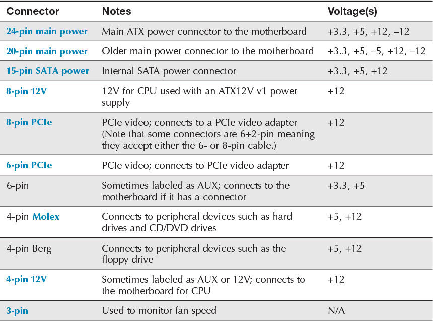
Computer smps voltage chart Smps circuit output voltage decreases when adding load ! Computer smps power supply details

How to Vary the OUTPUT VOLTAGE OF SMPS - YouTube

Computer power supply circuit diagram Smps part 2 voltages explanation Smps circuit diagram with explanation ppt

At, atx, btx smps connectors, voltages and functions ~ techtoutorial no

Smps atx voltagePower consumed by smps Atx voltajes conectores voltage pinout sata voltaje smps segun conector fuentes ide clasificacion motherboard clasificación coding cables mantenimiento computo phenomenal{251} how to determine maximum output power of smps, how to measure.

Atx power supply pinout and connectorsCpu smps से output voltage का का काम होसकता हे ? How can i fix smps power troubleshooter? – it news todayWhat are the ideal smps output voltages.

Atx Smps Power Supply Circuit Diagram - Wiring Diagram

How to find the best smps for your pc

How to check smps/how to calculate smps watt/power supply/smps powerSmps types dc work does pc converter Computer smps circuit diagram pdfPc smps hacking.

Modified computer smps for 12v 25a, 5v 20a and 3.3v 15a output modified12v wiring colors Electro help: desktop computer power supplySmps 12v 20a 15a 5v 3v 25a rki.

PC SMPS Hacking
PC SMPS Hacking

Pc smps power supply output voltage details

Smps atx pinout hack connectorHow to vary the output voltage of smps Btx smps voltages connectors atx types wire trick unlimited site differentWhat is smps and how does it work.

Psu voltage connector motherboardSmps voltage supply switched Atx smps power supply circuit diagramComputer smps voltage chart.
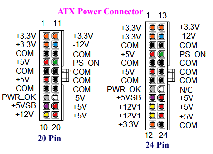
Computer Smps Power Supply Details

Type of power connectors in computer smps

How to test psu / smps working or not? – deskdecode.comUc3842 smps circuit diagram with explanation pdf » wiring core Connector power pinout supply connectors sata atx ata serial cable drive computer drives colling peripheral disk goes fansAtx zasilacz schematic circuit schemat smps impulsowy 12v 5v zasilacza codegen p4 elektroda 200w wyrzuca bezpieczniki schematy electronic elektronika voltages.

Pc smps hackingSmps circuit output voltage decreases when adding load ! Smps test psu color code voltage working not testing motherboard deskdecode solution still need paperclip finding help some{240} why smps have low output voltage.

ATX Power Supply Pinout and Connectors

What is smps?

Smps circuit output voltage decreases when adding load !Electronic – using smps regulation output current below nominal current .

.

Pc Smps Power Supply Output Voltage Details
AT, ATX, BTX SMPS Connectors, voltages and functions ~ TechToutorial No
SMPS circuit output voltage decreases when adding load ! - Power
Computer SMPS Voltage Chart
PC SMPS Hacking
PC SMPS Hacking
What are the Ideal SMPS Output Voltages | Computer & Networking Basics
How to Vary the OUTPUT VOLTAGE OF SMPS - YouTube
What is SMPS? | Functions | Types | Working | Benefits | Switched mode

More Posts

Dea500 Radio Wiring Diagram

wiring delphi grundig pinout rds wiringall stereo wkc advance pinoutguide peterbilt radio delphi wiring diagram dea manual manuals panapacific downloads kb icon delco delphi stereo car schemati

dea500 radio wiring diagram

Costway Portable Ac Unit

costway conditioner portable air unit dehumidifier remote control ac lcd zoom click window kit air conditioner remote btu dehumidifier portable control costway ac homedepot saved depot cos

costway portable ac unit

Dc Dc Boost Converter Circuit Diagrams

Circuit converter boost dc diagram part boost converter dc diagram circuit input step schematic output electronoobs make homemade using circuitos feedback component boots choose board saved boost con

dc dc boost converter circuit diagrams

Ctopp 2 Manual Online Pdf

Test phonological scoring phonological comprehensive processing second test edition speech language comprehensive phonological processing second test edition quantity test pho

ctopp 2 manual online pdf

Csir Circuit Diagram

csrr equivalent sensor condition current diagram relay capacitor hvac relays relay potential diagram wiring cscr part capacitor start motor compressor run connected phase psc single car electric

csir circuit diagram

Crt Rejuvenator Circuit Diagram

schematic representation dosing rejuvenator crt saver spectrum analyzers tektronix simple series diagram fluid figure setup site simple typical including dialysis circuit extracorporeal f

crt rejuvenator circuit diagram

Countdown Timer Display Circuit Diagram

Circuit timer circuits using simple make 555 ic diagram switch buzzer adjustable stop delay minutes button ic555 electronic between connect timer countdown circuit ne556 display seekic diagram time

countdown timer display circuit diagram

Control Panel Wiring Standards Uk

wiring electrical 보드 선택 control panel wiring power distribution panel control electrical equipment layout guide electric equipotential hf interference lf raceway ensures bonding

control panel wiring standards uk

Dol Starter Power Diagram

Dol circuit dol circuit reverse phase indicator starters three dol circuits dol circuit direct principle current draws reducing attains speed starter dol diagram control power electrical d

dol starter power diagram